The View Up Here

Random scribblings about kites, photography, machining, and anything else

  • Flickr Gallery

Archive for November, 2016

Building the MS Alice Microphone – Part 2

Posted by Tom Benedict on 23/11/2016

This is the second half of a two-part article describing my build of the mid-side Alice microphone, following the Instructable written by Jules Ryckenbusch: Build the MS Alice Stereo Microphone. In Part 1 of this article I ran through how I was planning to build it (mostly following the same steps I used in another two-part series I wrote about another of Jules’s Instructables, Modify a Cheap LDC Condenser Microphone, namely: BM-800 Microphone Conversion Part 1 and Part 2.) I also covered my design for the saddle and post that holds the three capsules in the particular orientations required for Jules’s MS microphone build. (Jules used a different method, using PVC pipe, which you’ll see in his Instructable if you decide to build one of your own.)

Since writing Part 1 all the bits and pieces came in. I was eager to see how the 3D printed saddle and post turned out, and how well the TSB-165A capsules fit.

M-S Alice Capsule Saddle and Post - Unpopulated

I designed the cavities for the capsules at-size, meaning I didn’t leave any slop for fit. The plastic Shapeways uses to make their least expensive printed parts is described as “strong and flexible”. I took them up on that, figuring the part would flex enough to allow the capsules to snap into place. It worked like a charm.

M-S Alice Capsule Saddle and Post - Populated

The fit is snug, but not snug enough to hold the capsules in use. As with my first Alice, I glued the capsules into the saddle with E-6000 adhesive.

I’m a little disappointed with the handling noise on my first Alice mic. I chalk some of that up to the metal saddle and post, but some of it I chalk up to the relatively stiff wire I used to connect the capsule to the PCB. It was stiff enough that manipulating the wire wound up breaking off one of the ground tabs from the TSB-2555B capsule I used on that mic. Rather than repeat that experience, and in an effort to reduce conduction paths for handling noise, I gutted some of the Mogami cable I use for all my microphone projects and used the wires to connect the capsules. (NOTE: It didn’t actually affect handling noise that much. After thumping various bits of the mic, I’ve come to the conclusion the dominant frequency of the handling noise is driven by the resonant frequency of the mesh in the headbasket.)

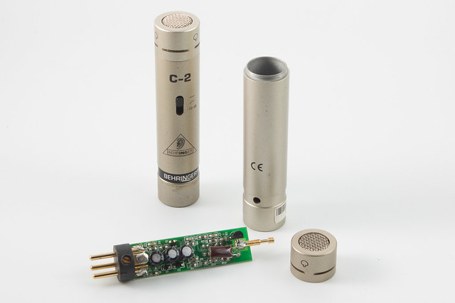
I already had two Pimped Alice PCBs built, tuned, and ready to go for this project. The remaining steps were to screw one board onto each side of the mic frame, solder the capsule wires to the boards, solder the four 0.022uF capacitors between the ground pin (pin 1) and the remaining pins of the XLR connector (2, 3, 4, and 5), and to solder wires between the XLR and the PCBs.

M-S Alice Internals

Since I oriented the two capsules of the figure-eight mic side-by-side, they won’t fit inside the headbasket with the foam liner in place. So I stripped the foam out before closing up the mic.

The very last step was to build the 5-pin XLR to dual 3-pin XLR splitter cable. There are a number of ways I could’ve done this, but I followed (mostly) Jules’s build on the cable as well, using separate Mogami lavalier cables for each channel. This is a wonderfully floppy wire, and does an excellent job of reducing handling noise transmitted through the cable.

The one change I made to Jules’s design was to jacket the central eight feet of cable in a woven sleeve to keep it from tangling.

M-S Alice Patch Cord

I left the last foot and a half at each end loose, though, to take advantage of the wire’s floppiness. (Hey, that’s actually a word spellcheck recognizes!)

And at long long last I’m able to play with mid-side recording and compare it against my EM-172 based SASS.

SASS vs. M-S Comparison

https://soundcloud.com/tnbenedict/kiholo-bay-sass-vs-m-s

Big big thanks to the following for making this all possible:

  • Jules Ryckenbusch – for writing the two Instructables that got me going on these microphones
  • Homero Leal – for coming up with the PCB layout for the Alice boards used in Jules’s Instructables
  • Scott Helmke – for designing the Alice circuit in the first place
  • Ricardo Lee and all of the above – for their endless patience with all of my questions and what-ifs
  • Dr. Ing – for designing the Schoeps CMC-5 in the first place, without which none of this would exist

For my own contribution, here’s the link to the MS Alice capsule saddle and post on Shapeways. I’ve listed these at-cost, with no mark up (meaning I don’t see a dime of the 5.35 USD price tag at the time of this writing – labor of love).

Have fun recording!

Tom

Posted in Audio, Engineering | Tagged: , , , , , , , , | 16 Comments »

Building the MS Alice Microphone – Part 1

Posted by Tom Benedict on 11/11/2016

This is a short pair of articles that glosses over most of the details of how I’m building a self-contained mid-side (MS) Alice microphone into a Neewer NW-800 microphone body. Part 1 covers most of the design and preparation, and Part 2 will cover the build.

The reason why this pair of articles is so brief is that most of the nitty-gritty was already covered in another pair of articles: BM-800 Microphone Conversion Part 1 and Part 2. The major differences between that microphone and this one are a change in capsules (Transsound TSB-165A instead of a Transsound TSB-2555B), the number of capsules (three instead of one), the number of Pimped Alice boards (two instead of one), and a change tof XLR connector (5-pin rather than 3-pin).

With the exception of how I’m planning to mount the capsules, all of this follows the Instructable written by Jules Ryckenbusch: Build the MS Alice Stereo Microphone. That’s the real reference for this build, so if you decide to build one of these yourself be sure to follow Jules’s notes.

The easy stuff first:

When I built my first Alice microphone I built three PCBs rather than just the one I needed, so I already have two Pimped Alice boards ready and waiting in the wings. I was on the fence whether to build a second mic around a TSB-2555B capsule or go straight to the MS Alice. After some recent field tests, I decided to commit the two boards to an MS Alice.

Jules pulled a neat trick for getting two signals out of a single XLR connector: use a different XLR connector! In his build he replaced the 3-pin XLR that came with his BM-800 microphone with a 5-pin. The two outputs share a common ground, but have independent signal pins. I’m following this part of his plan to the letter. (As a side note, this also gives me a spare 3-pin XLR connector to use when I finally build out my parabolic mic. New project in the works!)

The only things left to do were to order three TSB-165A capsules (done) and to figure out how to mount them.

Jules has a nice tutorial on how to build a 3-capsule saddle out of PVC pipe, but I had so much fun machining a custom saddle for my TSB-2555B capsule, I couldn’t pass up the opportunity to massively over-complicate life by designing a custom saddle for the MS Alice as well. Here’s what I came up with:

MS Alice TSB-165A Capsule Saddle

Which looks neat and all, but would be stupidly difficult to machine. It’s possible, provided you got rid of, or at least filleted the inside corner between the two side capsules, but it wouldn’t be fun. And since this is all about fun, I cheated. I sent it off to be 3D printed out of nylon. (If this pans out and there’s any interest, I’m happy to make the 3D model available for other people to print.)

So now I’m back to playing the waiting game. I’ve got parts coming in from Redco Audio (5-pin XLR to dual 3-pin XLR splitter cable), Mouser (smaller capacitors for the Alice boards to address the space constraint issue I ran into), Amazon (Switchcraft 5-pin XLR connector, NW-800 body, and associated doodads), JLI Electronics (three TSB-165A capsules), and finally Shapeways (the 3D printed mic saddle).

I’ll write the second half of this series once all the goodies show up.

Tom

Posted in Audio | Tagged: , , , , , , , , | 3 Comments »

A Lack of Noise Measurements

Posted by Tom Benedict on 10/11/2016

When I built the Alice / TSB-2555B microphone, my intention was to get out with my normal recording gear, bring the Alice along, and get some side-by-side nature recordings to demonstrate how good or how bad the self-noise on the Alice is.

I have yet to pull this off. But in the process I became utterly paranoid about my gear, and feared I’d somehow broken it. In the process I made a number of completely useless recordings in the Upper Waiakea Forest Reserve and out on the Cane Haul Road north of Honokaa. I got some really interesting bird calls and some halfway decent coqui frogs, but most of all what I recorded was what sounded for all the world like… noise… (I’m pretty sure it was wind, but I’m giving away the punch line.)

This finally led me to do a series of recordings in the back seat of my car, parked in the relative un-quiet of my yard, under what is finally a wind-free clear night. In the process I think I demonstrated the excellent noise characteristics of the Alice microphone, and I’m pretty sure I recorded my own heartbeat from the seat next to my gear. (Yes, I had the gain cranked up that high.)

I found that the Alice edges out the Primo EM-172 capsules for noise, potentially by more than -3dB. I also found that even at ten o’clock at night there are very few windows of time when cars aren’t going by on the nearby highway. (I also found there’s a limit to how long I can sit still, not tic, and breathe shallow.)

With my faith in my gear restored and an expectation of the performance of the Alice microphone, I’m planning to head out Friday to record inside a lava tube. It’s not the rain recording I’ve been trying to nail for the past several months, but if I manage to get water dripping from the roof into underground pools, I’ll count that as something pretty cool.

This also gave me the confidence to order all the parts to build Jules Ryckenbusch’s MS Alice microphone. I still have mixed feelings about how mid-side is likely to fit into how I record in the field, but I know I’ll have a good mic to try it with.

Tom

Posted in Audio | Leave a Comment »

Alice and Behringer Sitting In A Tree – Part 1

Posted by Tom Benedict on 03/11/2016

The field tests on my BM-800 Alice conversion will have to wait. Late last week I handed it over to a friend for tests I’m not equipped to make, including several mic comparisons. I’m eager to see (and hear!) his results.

Meanwhile my Behringer C-2 mics showed up. These are the ones I placed a bid on over at Ebay before I realized they were coming from Haifa, Israel. Despite the distance the shipping was actually less than FedEx charges to ship a letter-shaped package from the mainland US to Hawaii. (Go figure.) It still ramped the price of the mics up almost to market value, which on Amazon with its super saver free shipping basically means I could’ve ordered them new and had them weeks ago.

But they’re here. And they’re mine. And… to be honest they’re in pretty ratty shape. One of them had something loose in the capsule. If you pointed the mic up and shook it, it made a hellish noise and clipped constantly. Turn it upside down and shake, and you hear something rattling around. The other mic has something massively wrong with its circuit board. It sounds for all the world like a Huey is hovering overhead. Bup bup bup bup bup bup bup… It never ends.

So long story short, I don’t mind gutting these things and building something new. In the short term I put the good capsule on the good mic body so I have one working mic to play with. The other one I started taking apart.

Behringer C-2 Capsule Removed

These have interchangeable capsules, though I don’t know if Behringer (or anyone else) makes any other capsules for it. The one that came with my mics is a hypercardioid. (At least that’s what the icon on the side of the capsule looks like.) Given the size of the vents at the back, I can believe it.

Underneath the capsule is a white plastic plug with a pogo pin centered in it. Not much to look at. And no real clue how to open things up past there.

To gain access to the innards of the mic, peel back the the “Behringer Condenser Microphone” name tape at the base. This reveals a small set screw that should be familiar to anyone with Switchcraft XLR connectors. Screw the set screw all the way in. This releases the XLR connector from the body. Next, center the pad/high-pass filter switch and pull the switch button out with needle nose pliers. Finally, push on the white plastic plug to expose the circuit board.

Behringer C-2 Stereo Pair - Partially Disassembled

Here’s what’s inside:

Behringer C-2 PCB Top

Since one of my mics has a damaged board, rather than figure out how to tweak what’s already here, I went ahead and tried to figure out how to pack a Pimped Alice into the same board space. I started by taking measurements.

The board is 15.5mm wide x 52.35 mm long, and is 1mm thick. The thickness is important because the board slots into the white plastic insert. One nice thing about this method of mounting the board is that there are no screw holes, and except for the humongous XLR pins and the 2mm area that slots into the plastic insert the rest of the real estate on the board is free. The board is mounted just below the centerline of the mic, so there’s vertical room as well. Up to a point, anyway. Those capacitors are 6.5mm diameter x 8mm tall. Nothing bigger than that will fit, even centered on the board.

There’s really not enough room to use through-hole components everywhere, so I converted most of the Pimped Alice circuit to 0805 SMT components. The exceptions are the filter capacitors, the 1Gohm resistor, and the FET.

There seems to be some resistance to using surface mount technology for DIY mics, but SMT has been used for over a decade for DIY robotics and electronics. I’ve built AVR processor boards using SMT components, and figured this wouldn’t be much different. With the exception of the big filter caps and the FET, that’s how Behringer built the original board for the C-2, so I figured it was a safe way to go. As soon as I have a new PCB layout, I’ll send it out for fab.

Meanwhile I started taking apart the capsule. Just looking through the grille, it seems like the C-2 uses a Transsound capsule similar to the TSB-165A Scott Helmke used in the original Alice.

Behringer C-2 Capsule Front

I started by removing the back plate. This is just pressed into place, but it’s a bear to get out. I eventually removed it by gripping it by an inside edge with needle nose pliers (pushing outward), and spinning it out. It took a couple of attempts, but it came apart.

The rear side of the capsule has an open cell foam washer in it, presumably to provide wind protection and to act as a delay plate to shape the hypercardioid pickup pattern. With the washer removed, the back side of the capsule is visible, held in place by a brass retaining ring

Behringer C-2 Capsule Back - Baffle Removed

The holes in the ring are really tiny. My existing pin wrench didn’t work, so I used an old divider with dull points as a pin wrench. There’s a bit of red enamel to prevent the ring from backing out, which took a little force to crack. Once that was done, though, the ring backed out easily. (I’ll need to be sure to apply a fresh bit of enamel when I get the new capsule installed.)

Behringer C-2 Capsule Disassembled Back

Behringer C-2 Capsule Disassembled Front

I was hoping the capsule was a Transsound TSB-165A, the same one Scott Helmke used in his original Alice microphone. Unfortunately it’s not. The capsule in the C-2 is 16mm in diameter x 6mm thick. The TSB-165A is 16.5mm x 8mm. But after some poking around on the JLI Electronics web site I think I found a match: the TSB-160A. The specs are almost identical to the TSB-165A, so it should play nicely with the Alice circuit (yay!), but the form factor matches what’s in the C-2. I’ll order a pair of these when I place the order for the 165A capsules for my MS Alice.

Behringer C-2 Capsule Mesh Outside

Another concern with the C-2 capsule holder is how the capsule is recessed, and how close the edges of the holder come to the input ports on the capsule. From my experiences with my first rev of mic bodies, I know that can color the sound enough to hear it. I’d like to open this up, if possible. It’s a simple enough job on a lathe as long as I can get the grill out.

Behringer C-2 Capsule Mesh Inside

The grill looks like it’s a two-layer mesh that’s either glued or soldered into the capsule holder. That should be easy enough to remove with heat, one way or the other. I might even be able to re-use it if I’m not too rough getting it out.

The grill serves two purposes. First and foremost, it’s an RF shield to keep stray electromagnetic radiation from getting into the signal path. Second, it helps to keep the capsule free of debris. Third, some manufacturers will stick enough mesh in front of the capsule to act as a rudimentary pop filter, and at least reduce the effect of wind. The problem with that third purpose is that you need a lot of tight mesh to pull that off. Enough so that it colors the sound of the mic. Not surprisingly, one of the more obvious mic mods is to remove a layer of mesh from the capsule housing.

But given how open the outer mesh is, I’m afraid it will make the mic prone to RF interference. For now I’ll leave it alone.

The next steps are to finalize the design of the new board, send it out for fab, and source all the components and capsules. But before I can finalize the board design I want to see if I can add in one of the features of the C-2: The switch on the side of the mic lets you select a high pass filter or a -10dB pad. If I can find the real estate on the board to accommodate the switch and the components necessary to add these into the Alice circuit, I will.

Tom

Posted in Audio, Electronics, Engineering | Tagged: , , , , , , , , , , , , , , | 1 Comment »