The View Up Here

Random scribblings about kites, photography, machining, and anything else

  • Flickr Gallery

Converting Older Crown PZM Mics to P48

Posted by Tom Benedict on 04/12/2022

Several weeks ago I made an attempt to buy a set of Crown PZM-6D mics off of Ebay and Reverb. What I wound up with was a PZM-6LPB, a PZM-6LPG (essentially the same mic but one black and one gold), two PZM-6S mics, and PX-18 power supply. For anyone who’s familiar with Crown’s older PZM mics, you can probably see the problem: None of these PZMs will plug directly into a recorder. They need to go through that PX-18 power supply to convert P48 to the 18v the PZM needs. And I only got one.

Rather than pick up three additional PX-18 (or PA-18) power supplies, I decided to convert the PZMs to be able to plug straight into a recorder without the need for a dedicated power supply, just like a PZM-6D. It keeps the bag neater and considerably lighter!

The schematics for the Crown PX-18 and PA-18 power supplies leave out an important detail: what the wires coming from the capsule actually do. They’re just labeled by color. I finally tracked down the entire schematic of a PZM+PX-18 in the manual for the Crown SASS-P II. Turns out each channel is basically an older style Crown PZM with the guts of a PX-18 wired directly into them.

Lo and behold, the early PZM capsules have a FET built into them and bring out Drain, Source, Gate, and Shield separately. David McGriffy came up with an extremely simple circuit for driving an electret+FET capsule using P48. It’s a resistor and capacitor and is affectionately known as SimpleP48. Ricardo Lee wrote a really good document describing the SimpleP48 circuit, which you can download here. I did my own writeup when I built my first Primo EM-172 based mics. David cautions that you shouldn’t go over 10m of cable with this circuit but I’ve used it on 75m cables without issue.

A lot of electret+FET capsules (e.g. Primo EM-272) bring out only two terminals, tying Gate and Source together or, in the case of the EM-272, tying Gate, Source, and Shield together. You can still use the SimpleP48 circuit with a three-wire (or four-wire) capsule by tying Gate and Source together yourself and treating the whole thing like a two-wire capsule. This is what Jules Ryckebusch did for the Ambisonic Alice project, which used four JLI-2590A capsules. (This really is a versatile circuit!)

In the case of the Crown PZMs, shield is soldered to XLR Pin 1, red is soldered to XLR Pin 3, and the black and white wires are tied together and soldered to the connection between the capacitor and resistor in the Simple P48 circuit. I’d include a schematic but this is about as simple as it gets.

To finish the circuit, though, I needed to find a good value for the resistor. Since I had a known working system, the PZM+PX-18, I used it to find a decent value. Plugged into a Zoom F6, the PX-18 delivers 13.1v to the PZM capsule, measured at the output of the PX-18 with the capsule plugged in.

Several years ago I built a SimpleP48 circuit with a 4.7uF capacitor and a 500k pot. I used this setup to dial in 13.1v at the output with the PZM attached and then measures the resistance of the pot, which came out to 111k. I have a stash of 100k 1% resistors on-hand, so I populated four XLR connectors with 4.7uF capacitors and 100k resistors. This ov-drives the capsule slightly but it works fine and is still well under the 18v listed voltage.

EDIT: One of the drawbacks of buying old mics is that unless you manage to get them as matched pairs, they rarely are. In the case of the PZMs I bought, no two mics were even close. It occurred to me, though, that shorting the black and white wires essentially bypassed the capsule’s internal resistor, which turned out to be a 10k. If, instead of tying the two wires together directly I added a 10k pot between the white wire and the Simple P48 resistor, I should be able to tweak the gain of each mic. I found some small 10k pots in my stash and added one to each of the four mics.

I taped all four mics to the wall of a walk-in closet and aimed a speaker at them from roughly a meter away. A 1 kHz tone on the speaker let me dial in the gain on all four mics until I had them within 0.2dB of each other. So now I’ve got two match pairs, one with a HF boost and one without, and the two pairs are matched to each other. Bonus!

Before clipping the connectors off all four of my mics I converted just one so I could run some comparisons. The SimplePZM has a hotter output than the one going through the PX-18. (No surprise here. The PX-18 has a transformer output and no active circuitry.) In my test, balancing the two mics required +46dB of gain on the PZM-6LPG+PX-18 and +16dB of gain on the PZM-6LPB+SimpleP48, so the new configuration, the SimplePZM, requires 30dB less gain out of the recorder’s preamps.

The SimpleP48 circuit has no active components so the only source of noise in it is the Johnson noise from the resitor. My guess is the bulk of the noise in the circuit is coming from the capsule and its in-built FET, which is common to both configurations. Essentially, the noise floor of the SimplePZM should be identical to or better than the noise floor of the PZM+PX-18. Coupled with the lower gain requirements and it’s starting to look (and sound) very attractive.

The side-by-side tests I made didn’t show any difference in response out of the converted mic, which is what I expected. With all of this in hand I clipped the connectors off the remaining mics and soldered the SimpleP48 connectors on in their place.

What’s next? To compare all of these against the pressure zone microphones I built, following the instructions in Jules’s Build a PZM Microphone Instructables article, of course! But that’s for another time.

Tom

Posted in Uncategorized | Leave a Comment »

The EM-204 Quad – Better Than I Remember

Posted by Tom Benedict on 06/10/2022

Recently someone asked if anyone had any real-world experience with the ultrasonic response of the Primo EM-204 capsule. I happened to have a microphone I built a while ago with 204 capsules in it so I offered to run a test. I even had an EM-258 pencil microphone to do an A/B with since the ultrasonic response of the EM-258 is better understood. After a couple of false starts I did a side-by-side comparison of the two by jingling keys, dinging small wrenches, etc. To my surprise the EM-204 had an extended ultrasonic response that went well above 60kHz! It didn’t have quite the range that the 258 has but it was still impressive. Even better, it’s a cardioid capsule, whereas the EM-258 is an omni, so it brings something new to the table for ultrasonic mic builders.

A/B Spectrogram of EM-204 (top) and EM-258 (bottom)

Years ago a fellow recordist pointed out that simply having an ultrasonic response isn’t enough. It has to actually sound good when pitch-shifted down. So did a high-pass at 10kHz to get rid of most of the human-audible sounds, pitch-shifted both tracks down by four octaves, and listened to them. They both sounded pretty good! Not identical, obviously, but neither one was bad.

This made me take a second look at the microphone I’d used for the test. It’s one I built several years ago when I first ventured into spatial audio. It has four EM-204 capsules in it, arranged as a double-XY: two capsules point forward, each 45 degrees off of center from each other, and two point behind, also spread 45 degrees off of center from each other. The result is a microphone with four capsules spaced evenly around a circle.

When I built it the idea was to have something that I could use any number of ways: Flip the phase on the rear capsules and add to the fronts and it’s a Blumlein pair. Rotate it 45 so there’s a center capsule, flip the phase on the right capsule and add to the left, and it’s a double mid-side. Or just use all four capsules as-is and treat them as an Ambisonic microphone with no height component. It was a neat idea! I just never really used it.

The reason was that shortly after completing the microphone I compared it against another microphone array I knew and liked: my DIY SASS. It uses another Primo capsule, the venerable EM-172. My DIY SASS was my first “real” stereo array and through hundreds of hours of recordings I fell in love with its sound. So much so that, as it turns out, when I listened to the comparison between the SASS and the EM-204 Quad, I disliked the sound of the quad and, in disappointment, put it in a box and stuck it on a shelf.

Since then I’ve built other quad capsule mics including the Ambi-Alice, a 2nd order Ambisonic, and even a 1st order Ambisonic that used EM-204 capsules. Ironically, the Ambi-Alice became my mainstay ambience microphone and the SASS joined the EM-204 Quad on the shelf. I still prefer the stereo image of the SASS to coincident arrays like the Ambi-Alice, but the versatility of the Ambi-Alice eventually won me over for my drop-and-recover sessions.

The jingly key session was a good wakeup call. Listening to it, I was struck by how good the EM-204 Quad actually sounded! So I took it out again and, during my lunch hour today, went recording in the park.

In hindsight, I don’t think the EM-204 Quad ever really sounded bad. It just didn’t sound like my SASS. No surprise, the SASS uses two omni capsules in a partially baffled boundary array. The EM-204 Quad is four coincident bare cardioids. There is practically no similarity between the two designs or the stereo image they produce. Back then all I heard were the differences between them and, rather than treating them as two different things, equated different with bad. The SASS had become my auditory standard and the EM-204 Quad just couldn’t measure up, despite the fact that it was a really good sounding mic in its own right.

I’m glad I’ve had the opportunity to get the EM-204 Quad back out in the field. It has a lot going for it, even in comparison to the Ambi-Alice. The array radius of the Alice is 19.6mm. The array radius of the EM-204 Quad is 7.3mm, almost a third of that. This affords it more spatial accuracy at higher frequencies. It has an ultrasonic response out past 60kHz which makes it interesting from a sound design standpoint. And, being built into a BM-800 body, it’s quite compact. I even had the foresight to use a 10-pin XLR on it so it plays nicely with my current extension/splitter cable scheme. It’s got a lot going for it.

I think my next step is to venture further afield than the park behind my work. Maybe it’s time to hike out into the forest again to record the evening chorus.

Tom

Posted in Uncategorized | Leave a Comment »

Capsule-Swapping a Snowball

Posted by Tom Benedict on 22/01/2022

I finally finished a mic mod I started about four years ago: a capsule swap on a Blue Snowball Ice.

Yes, I’m aware this is probably the least useful mic mod out there, but… Snowball! And yeah, I know four years to finish this is a little long, but it wasn’t exactly my top priority (’cause… Snowball!)

Blue Snowball Ice

For anyone else thinking of doing this, the capsule in the Snowball is a 14mm electret with an in-built FET that bears a striking resemblance to a JLI-140A-T. It uses a three-wire connection to the mic’s PCB, one each for the FET’s drain and source, and one for gate/ground. This means any electret with an in-built FET with all three pads brought out should work just as well (emphasis on “should”).

Snowball Original Capsule (pardon the blurry photo on the left… rushed!)

The Snowball is completely connectorized, meaning you can mix and match as long as you use the right connector. The one for the capsule appears to be a 3-pin Molex KK 254 series female. I didn’t have the right one in my stash of parts so I liberated one off of a junked PC. It’s the same one that’s used on 3-pin case fans and since the cable is so short, I had no problem obtaining enough length from it to use for the project.

Original Snowball Capsule with Cable

The capsule in the Snowball is held in place by a silicone mount that sits on three posts. This is both a blessing and a curse. It means a single part is required to mate a new capsule to the mic body, but… you do have to design and build that single piece!

Snowball Capsule Mounted in Place

I’ve built a couple of microphones around the JLI-2590A that turned out really well. The 2590A is essentially a JLI-25AXZ-G3 with the addition of a FET and de-coupling capacitors. It sounds practically identical to the JLI-2555B, which has been used in any number of vocal microphones. There’s plenty of room inside the Snowball for the 2590A, so that’s what I chose for this build.

Electrically and sound-wise, it dropped right in. Mechanically, the thing is hruge compared to the original! There was no way to re-use the original silicone mount, so I 3D printed a new mount out of TPU that holds the 2590A in the right place. Unfortunately, I can’t print TPU at home so I had to have one printed for me.

JLI-2590A Snowball Mount – Rendered

Quick rant: When working with materials, a fair question to ask is, “What’s the material’s hardness?” Unfortunately, there’s no one “right” scale. For metals, Rockwell, Brinell, or Shore hardnesses are typically quoted. For plastics, Rockwell, Shore D, or Shore A are typical, depending on whether you’re talking about a hard thermoplastic or a soft elastomer. For soft rubbers like silicone, Shore A durometer is a useful scale. You can typically look up the hardness of the material you’re looking at and try to match it to the hardness of another material you’re considering. The only problem? I couldn’t find any hardness information for 3D printed TPU parts anywhere! This makes it a real bear to work with this stuff.

And as it turns out, the TPU part I had printed was extremely hard compared to the silicone part I’d removed. Too hard for it to fit over the mounting pins in the Snowball. I addressed this by cutting slits in the parts that fit over the pins but had I known this I would’ve designed it completely differently. Material manufacturers, please quote material properties in your spec sheets so designers can design accordingly!

JLI-2590A Mounted

The inside of the Snowball is about as bad a design as you could possibly come up with for a cardioid mic: lots of obstructions and a big plate right behind the capsule. They make up for some of this by having a big chunk of foam behind and around the capsule to act like some kind of a delay plate. My guess is the polar pattern of my capsule-swapped Snowball is atrocious, but I didn’t even try to evaluate that.

With the new capsule in place, it was time to close the mic back up and test.

JLI-2590A Installed

I don’t have the cleanest space in which to record lines at the moment so bear with me on any background noise or residual reverb in the space. This is all about the mic, not about the sorry state of my recording space, after all:

https://soundcloud.com/tnbenedict/snowball-a-b-test

I leave it up to you to figure out which mic is which.

I could go into more analysis on this – comparative frequency response, noise floor, etc. – but I’m going to leave it here for now. This thing is not going to change the recording world. It was a fun project with a surprisingly good result, nothing more.

Now back to my XLR mics!

Tom

Posted in Uncategorized | Leave a Comment »

Orca OR-268 Review

Posted by Tom Benedict on 03/04/2021

Ever since the Zoom F6 was released into the wild, I’ve been interested in getting one. Interested, but not all that driven to do so. By that time I had my F8 and was quite happy with it, especially after the firmware update that added the advanced hybrid limiter functionality that first showed up in the F8n. Don’t get me wrong. I loved the idea of 32-bit floating point recording when I saw Watson Wu’s review of his pre-release unit, and Curtis Judd’s review of the F6 and his demonstration of how 32-bit floating point workflow can recover what would otherwise be either blown or overly quiet audio was beyond convincing. In the back of my mind, though, I couldn’t help thinking that proper gain staging with my F8 would get me 99% of the way there. So why get one?

In the end, what finally convinced me to get an F6 wasn’t that it could record 32-bit floating point audio. It was the chronic lower back injury I’ve had since I was nineteen. Each time I hiked out with my F8 it was a little harder and I came back a little more broken. I took steps to lighten the load as much as I could – replacing my stand with a carbon fiber tripod, stripping down my F8 bag and finally replacing it with a much lighter one for hiking, re-thinking how to distribute the weight so it spared my SI joints – but eventually I realized a lighter recorder would be a real boon.

At this point I’m sure no few people would tell me to get a handheld and a pair of external lavs, but the mic I’ve been reaching for more and more these days is a first-order ambisonic. That’s four channels at least. If I run that and my SASS at the same time, that’s six. Oh… Wait a minute…

The Zoom F6, with batteries, comes in just over 500g. If I could find a lightweight bag that let me keep the whole thing under 1300g I’d be able to hike farther and/or hurt less at the end of the day. And yeah, 32-bit floating point lends itself to the drop-and-recover style recording I’ve gravitated towards in order to work around my vocal tics. I placed the order for the F6 and started looking for a bag.

As luck would have it, a fellow field recordist was selling his barely used Orca OR-268, a bag designed specifically for the F6. I’ve been a fan of Orca bags ever since I got my OR-280 for my Zoom F8, so I jumped at it. As luck would have it, the bag and recorder arrived on the same day. I got busy setting up both.

It goes without saying that the OR-268 is a good deal smaller than the OR-280, which is already on the small side of things for a sound bag. But the construction of the OR-268 is also lighter overall. While the OR-280 has an internal frame that the side panels zip up over, on the OR-268, the frame more or less is the bag. There’s a front and rear pocket and a strip that zips around the sides and bottom, but that’s about it.

The bag does add some bulk to what is otherwise a really tiny recorder, but that’s not really that unusual. The OR-280 dwarfs the F8. If anything, the difference in size is less noticeable with the OR-268 and the F6. There’s really just enough room around the recorder to fit a bunch of XLR cables and an L-series battery (which I don’t currently use, so you won’t see one in any of the photos in this review.)

With all the pockets and panels unzipped, the structure of the bag is visible. It’s two plates with big gaping holes in them, separated by four posts. The whole arrangement is actually more rigid than the internal frame of the OR-280. I like the design a lot.

What I’m not as keen on is the suspension system for the recorder. I think that the designers at Orca were a little flummoxed by the positioning of the rails on the F6. (I can understand! I’m a little flummoxed, too. Why are they on the bottom and not on the front face like every other recorder? Zoom, help me out here.) The way the bag is designed, Velcro loops that are attached to the top posts somehow loop through the rails on the bottom of the F6, and nylon webbing with snap clips loop through the rails at the back of the unit to hold it into place. I futzed around with these for the better part of an hour before giving up in frustration and rolling my own arrangement.

In addition to the rails on the bottom of the F6, it’s got four mounting screws on the top that can be used to attach a 1/4″-20 camera mount to bolt the F8 directly to the bottom of a camera. I don’t intend to use mine that way, so I figure the screws are fair game for attaching double-sided Velcro strips to the top of the unit.

Practically every piece of blue cloth in the OR-268 bag allows Velcro to attach to it, so with the strips installed the F6 locks right into place where I want it. I still used the clip straps on the bottom rails to further secure it in the bag, though. With all six attachment points in place, the F6 doesn’t shift and won’t fall out if the bag is inverted.

I was concerned that the controls on the right side of the F6 wouldn’t be easy to reach once the recorder was in the bag, but this turned out to be less of an issue than I’d feared. The headphone volume control can be reached by sticking a finger down the right side of the recorder. (One more reason not to be too bothered by how much room there is around the recorder in the bag.)

Reaching the power switch takes a little more effort, but because the sides of the bag are so easy to unzip and re-zip, it really isn’t that much of a hardship and doesn’t add too many more steps to the process.

Fair warning, the rest of this is particular to the way I chose to set up my bag and may or may not have a bearing on how anyone else would want to.

Back when I was lightweighting my F8 bag, one of the changes I made was to modularize as much as possible. I already had lightweight single-channel cables that use Mogami lavalier wire, but with the exception of my SASS, which still uses one cable for each channel, my other dual-channel mics were all converted to 5-pin XLRs with 2-way splitters at the bag-end of the cable. At the same time all my quad-channel mics were converted to 10-pin XLRs with 4-way splitters. Since I planned to use my F6 with an ambisonic mic, I wanted to include a 4-way splitter in the bag.

Unfortunately, I’d built my splitters to work with the F8, which has the XLR inputs in banks of four on either side of the unit. To keep things neat, I made the legs of the splitters relatively short. So short, in fact, that there wasn’t enough length for the fourth channel to reach the other side of the F6. Rather than rebuild one of the ones I already had, I made a new one just for the F6. I wanted this one to have enough length in the legs to reach both sides of the F6, and since I had the option, I used low profile plugs.

It makes for a neat run and means I only need to make a single connection when setting up to record.

Since I’m primarily going to be using this setup for drop-and-recover recording, I shaved some weight off the bag by installing a pair of IEMs in place of the headphones I normally carry with me when recording. I like headphones better, especially when monitoring, but since I’d only use the earbuds to set things up before walking away, I decided it was a fair compromise.

For those times when I plan to monitor while recording, I can always bring my headphones and plug them in in place of the IEMs.

Which brings me to the last point about the OR-268: Despite its smaller overall size, it has loops in all the right places to attach it to the OR-40 harness I have set up for my OR-280 without having to change any settings. A full harness is massive overkill for a bag that weighs less than 1500g, but if it means I can hike a little further or hurt a little less at the end of the day, count me in. And for those times I need to remain tethered to the recorder, the harness is a natural choice.

All in all I’m quite pleased with the OR-268 bag, especially after coming up with a better way to suspend the F6 in it. Unlike the Velcro straps in the OR-280, the ones in the OR-268 are permanently affixed to the upper posts. I’m debating unscrewing the top posts to see if I can remove them, but for now that’s just not a high priority. It’s time to get out and put it all to use!

Tom

Posted in Uncategorized | Tagged: , , , , , , | 2 Comments »

T47 – An Inexpensive Dynamic Mic

Posted by Tom Benedict on 01/12/2020

A while back someone pointed me toward a really good sounding dynamic capsule made by BTM called a T47. They had put it in a mic shootout with a bunch of other vocal mics and it actually scored quite high, despite it being a bare dynamic capsule with an XLR plug.

Based on the shoot-out I picked up two of them and then… failed to do anything with them for a couple of months. I call this the “reduce heat and bring to a simmer” phase of fishing for ideas. I had a vague notion that I wanted to make some mics for high SPL sources (e.g. bottom mic for djembe, intake and engine bay mics for cars, etc.) but I didn’t really know how I wanted to do it. I hemmed and I hawed, but eventually ideas started coming together and I wound up with the design for a mic body that I could 3D print.

If you haven’t noticed, 3D printing factors into a lot of my mic builds. My background is really in subtractive machining – what they call “take off tools” – but once I got into 3D printing I really fell in love with the idea of being able to design and fabricate shapes that would be difficult to impossible to produce any other way.

This was not one of those projects. I think I could’ve knocked these out in the shop in a couple of hours out of Delrin, aluminum, whatever. But… I’d drawn them up in CAD already, and with COVID restrictions in place I couldn’t guarantee the shop time necessary to turn these out. So I sent them off to Shapeways to print. Here’s what I designed:

And here’s what I wound up with:

I love it when a design comes together!

It’s pretty straightforward. There’s a Switchcraft B3M connector on the bottom and the T47 capsule on the top. In the original design for the mic body, it was threaded on the bottom to receive the XLR jack. But as I found when I received the first rev bodies from Shapeways, I had cut my tolerances too tight. The jack didn’t screw in!

Rather than re-make these, I ran a tap through the body so the jack would thread in. (13/16″-20 NEF for anyone who’s interested.) The second rev of the body has a clear hole and a hexagonal recess inside it to take the jam nut that comes with the B3M connector. Way easier and probably more secure in the end.

The bodies are a little chunky, but at just under 36mm diameter they still fit in the larger universal clip mounts. (Because of my use case, mine are more likely to be mounted with gaff tape, so I didn’t put too much thought into how to mount them.)

Anyway, if you’re interested in building one of these, you just need three things: the T47 capsule, a Switchcraft B3M jack, and the mic body. Here are sources for all three:

https://www.aliexpress.com/item/32866241871.html

https://www.mouser.com/ProductDetail/Switchcraft/B3M?qs=IF7nv7MIRJ3ZKk2bybYqmw%3D%3D

https://www.shapeways.com/product/B3SF4W4AB/t-47-mic-body?optionId=181791683&li=shop-inventory

P.S. … (Or should I call this Part II)

After building these I took them out to the highway and recorded cars passing by. I think I had about 53dB of gain dialed in. That was a lot for someone who’s used to dealing with condensers, but not killer for a dynamic. I did get a bit of background hum, though, and soon realized I was standing under some high tension power lines. Noise removal in Reaper took care of it (I used iZotope RX Spectral De-Noise), but I wondered if it was RF pickup. So I did some additional testing.

Any time you get noise on an input, it’s worth plugging in a 150-ohm dummy plug and working outward to find out where the noise is coming from. As far as I can tell, I was running into the noise floor of my recorder. It’s not bad, but with the gain that high it was noticeable. Just in case, though, I came up with a backup plan:

One of the big problems with 3D printing parts for electronics is that plastic can’t act like an RF shield. Sure, I could’ve printed these out of brass or steel or something, but that would’ve been prohibitively expensive. Given the design, I’d just machine them at that point. But last night I finally found something I’d been searching for for ages: conductive paint.

Conductive paint isn’t new, but back when I first searched for it I could only find it in aerosol cans or as high-VOC oil-based products. I live on an island. I can’t even get most vendors to ship batteries out here. Conformal coating? No luck. Spray paint? You have to be kidding me!

But the stuff I found, on Amazon no less, is water based, low-VOC, and relatively inexpensive:

I’m going to run my dummy plug tests again tonight with the cable and mic right next to an AC cord to see if I can get a worst case noise measurement out of the thing. If it sounds like I’m having RF shielding issues, my plan is to disassemble the mics, paint the insides of the bodies with the conductive paint, and reassemble them with a solid connection between the painted surface and pin 1.

Meanwhile, I’m happy to have two nice dynamic mics and a means to add RF shielding to any 3D printed parts in the future.

Tom

Posted in Uncategorized | 13 Comments »

Things I Like About the Zoom F8

Posted by Tom Benedict on 06/11/2018

I figure the progression of recording equipment I’ve used is pretty typical: I started with an inexpensive handheld, a Tascam DR-05, progressed to a four channel, four XLR input recorder, a Tascam DR-70D, and most recently bought a used Zoom F8 that I’ve been using for the better part of a year.

Most of the time when you change gear, there’s something you miss from the previous one. When I moved from the DR-05 to the DR-70D I added two inputs, added XLR jacks, added dual-level recording, etc. But I lost stereo-linking (the DR-05 only has one gain setting for both channels) and I lost deterministic gain (the DR-70D doesn’t tell you how much gain you’re applying, unlike the DR-05). I expected to face the same problem when I got the Zoom F8.

With the exception of the larger size and weight, though, I really didn’t lose anything. And what I gained was worth every penny. The more I dug through the menus, the more stuff I found that would make my life easier when I’m out recording. Here’s a fairly long laundry-list of the things I love about my Zoom F8 (with v.5 Firmware):

  • It has eight inputs. Every time I’m told I’ll never need that many inputs, I look back at the number of times I’ve plugged something into every single one. I’m constantly playing with different mics, different setups, different ways to record the world around me. Having eight inputs means I can plug in my SASS, a mid-side, an ORTF pair, and two spaced omnis all at the same time. It’s fun in a box.
  • It took the Tascam dual-level recording feature and made it better. When you set up dual recording on the F8, it splits the input and delivers it to two tracks. Every control is available on that second track. You can set it to a different gain level in case the first channel clips, but you can also set one up with a high pass filter and one without. Or one with a limiter and one without. One with a limiter and the other with -10dB gain as a “safety track”. Whatever you want, you can do it. It’s just another track.
  • You can set up four “groups” of gain control, so stereo or quad recordings all have their gains tied to a single knob. This was one I really missed when I moved to the DR-70D. Most of what I record is in stereo, so having the ability to link gains is massive. Even better, you can combine this with dual-level recording to have two pairs of stereo tracks from a single pair of inputs, each with their own gain knob.
  • The advanced look-ahead limiters that came with the v.5 firmware on the F8 work really really seamlessly well. I was surprised by how well these worked. I had the opportunity to use my F8 as an audio interface during a voice acting workshop (more on that in a sec), and during the live-directed battle emotes I was yelling loud enough to clip. But both of the directors told me it sounded fine. Even better, looking back at the tracks there was no sign of clipping. It’s smooth and seamless. (Quick side note: No matter how good your limiters are, you really don’t want to keep running into them. They’re insurance in case your gain was set too high, not a mode you want to operate in on a regular basis.)
  • The F8 can act as an audio interface. For a lot of people doing field recording, this won’t be a big deal, but I also do voice acting. It’s entirely possible to voice act into a recorder and load the tracks into a DAW afterward. I did that for some time with my DR-70D. But having the option to record through the F8 straight into a DAW, especially for a live-directed session, is awesome.
  • With the new v.5 firmware, the F8 can act as an interface while recording to SD cards! This came in handy for online workshops and would be great for online live-directed sessions. I could use my F8 as an interface to participate in the workshop, and I could record my own mic in one channel and the workshop as a whole in a second channel. I know it’s possible to make an interface talk to a DAW and to programs like Skype and Discord simultaneously, but this took all the risk out of it. I got native-quality recordings without the possibility of a software glitch costing me the session.
  • The input/output routing, combined with its ability to act as an interface, makes for a very powerful analytical tool. I’m beginning to get into measurement and characterization of the mics I’ve been building. The inputs and outputs on the F8 work great for injecting signals directly into a mic preamp, and when you combine them with an amplifier and speaker, can be used to measure the microphone as a whole. (That will be the topic of a future post.)
  • The F8 takes two SDXC cards. How you use them is up to you. You can record in PolyWAV on one card and individual WAV files for each track on the second, or you can record the ISO tracks on one and a stereo mix-down on the other, or WAV on one and MP3 on another, or any combination you can come up with. I use the second card as a backup and record PolyWAV to both. That way if I inadvertently erase a track or an entire day’s recording, I can recover from the second card.
  • The F8 can run off of eight AA batteries, but it also has a DC barrel jack and a four-pin Hirose for external power. The DC barrel connector is for an external AC supply (which is great when you’re using it as an interface) and the Hirose is for external batteries. I got a pair of Talentcell DC bricks that’ll each give me over 24 hours of recording time. I’m not a huge fan of the Hirose connector because I’ve had them fail at work, but if your gear is kept snug in a sound bag and not hanging off the back of a telescope, they’re pretty solid.
  • The preamps really are quite nice. When I went from the DR-05 to the DR-70D I got a 9dB (~8x) improvement in the equivalent input noise, which was huge. Going from the DR-70D to the F8 I got another 7dB (~5x) improvement. At -127dB EIN (unweighted), the preamps are really really quiet, which makes the +75dB of available gain on the preamps mostly useful without blowing up the noise floor.
  • But my favorite part of this whole thing is that you can save the state of the recorder as a configuration file that you can load again at some later date. No worries about missing a setting or forgetting to toggle something. I can plug in, turn on, and load the configuration of my choice. Ready to roll! Here’s the list of what I’ve got set up right now:
    • Mono Ch1 – Good for single sources, parabolic, voice acting
    • Mono Ch2 – Good for single sources, parabolic, voice acting
    • Mid-Side Ch12 – Mid-Side stereo mic
    • Mid-Side Ch34 – Mid-Side stereo mic
    • Stereo Ch12 – Left-Right stereo mic (SASS, ORTF, A/B, etc.)
    • Stereo Ch34 – Left-Right stereo mic (SASS, ORTF, A/B, etc.)
    • Stereo Ch1234 – For running dual stereo rigs
    • Quad Ch1234 – For running quad rigs like my spherical mic. All channels tied to one gain knob.
    • Dual Ch12-56 – Dual level recording setup for channels 1 and 2
    • Dual Ch34-78 –  Dual level recording setup for channels 3 and 4
    • Dual Ch1234-5678 – Dual level recording setup for running dual stereo rigs
    • Interface Ch12 – For when I’m using the F8 as an interface. My local mic goes on channel 1, the computer’s sound goes on channel 2

I’ve completely ignored the other half of the F8: that you can use it as a location mixer. Some of the mixer features of the F8 make it a really solid tool for doing location sound. But since that’s not really my forte, I can’t give you my take on it. As a field recorder, it’s excellent.

UPDATE: And just this morning, Samuel Greene from Zoom announced there’s a firmware update for the Zoom F8 (v.5.10E). And that’s one more thing I love about my F8: Zoom’s excellent customer support.


Posted in Uncategorized | 2 Comments »

Inexpensive “Stealth” Bag

Posted by Tom Benedict on 25/06/2018

Almost a year ago, I made a drop bag according to Andrew Jones’s instructions on Wavreport.com. This featured in the photo set for my DIY Parabolic Mic that I wrote about back at the beginning of the year.

Recently I found another use for it.

The bulk of my field recording is nature recording. I hike out somewhere remote, set up mics, and make stereo recordings in an effort to allow the listener to feel like they’re really there.

But sometimes I record the sounds of people: crowds, traffic, the hustle and bustle of life. For the most part, the birds and the beasties don’t care what my mics look like. But people do. Even when I’m out recording the sounds of nature, people will spot my mics, walk over, and ask what I’m doing. (Which, if you’re into the obvious, means they show up in my recording. So much for pristine nature tracks.) Sometimes it’s advantageous to conceal the equipment in order to make a “clean” recording.

Recently, I had the opportunity to record in three cities: Austin, Texas, Washington DC, and New York City. (To be fair, I’m heading to New York tomorrow, then back to DC later in the week.) I knew I wanted to be able to record street traffic, the New York Subway, and crowd sounds. I turned to Andrew’s Drop Bag.

"Stealth" Recording Bag - Closed

I didn’t follow all the instructions from Andrew’s build. Most notably, I didn’t modify the top of the bag. It makes the bag a bit of a pain to use when tweaking the settings on the recorder, but it means it can be zipped shut with no one the wiser as to what’s going on inside.

"Stealth" Recording Bag - Open

What is going on is a Zoom F8 recorder, a Talentcell lithium battery modified according to another of Andrew’s articles, two EM-172 omni mics clipped to the outside of the bag, and a set of earbuds for monitoring.

The bag has a pair of loops on either side of the front compartment that you can clip lavalier mics to.  I stuck the lav mic case in the front pouch to give it a little depth, and voila, it’s a partially baffled stereo array with almost the same mic spacing as a human head. Not a bad setup for making stereo recordings, and unless you’re looking for the mics they blend right into the bag.

The Talentcell does an amazing job of keeping the recorder powered. Even after recording aggressively for several days, I have yet to reach the limit of the Talentcell battery.

Sound pressure levels in cities vary wildly, from the hushed tones of a museum crowd to the scream of a train entering a subway station. One of the nice features of the Zoom F8 (and of the Tascam DR-70D I used before) is the dual recording feature: Set the inputs for the mics up for the quiet sources and the backup tracks for the loud sources, and pick the appropriate track when curating the sounds in post.

At some point, I’ll order a second one of these and do Andrew’s full build on it. But I’m leaving this bag as it is. It’s just too handy for this sort of thing.

Posted in Uncategorized | 5 Comments »

34mm LDC Alice

Posted by Tom Benedict on 22/04/2018

I built a new vocal microphone!

Up until now all the vocal mics I’ve built have been based on the Schoeps CMC 5 circuitry and a Transound electret capsule. The first was back in September, 2016, when I made my first Alice, based on Jules Ryckebusch’s Instructable. Almost a year later I built three more along similar lines using BM-700 donor bodies and the Transound TSB-25AX capsule. That first one I built is still my main vocal mic, but I’ve been using all four in one form or another ever since.

This time I wanted to try something different. I’ve wanted to build a 34mm non-electret condenser ever since I started dabbling in voice acting. A combination of events finally let that happen.

The first was finding some relatively inexpensive 34mm capsules on Ali Express back in December, 2017. I wound up getting one with the plan of developing a charge pump board to go with the Alice boards I’d used on the last set of mics. Before I could do that, though, a long-term project at work took my full attention and I had to set the capsule aside.

Around the same time the work project began ramping up, Homero Leal posted a new version of his Pimped Alice board to the Yahoo! micbuilder forum. This one included circuitry to bias a non-electret condenser capsule. (Yahoo!!) I ordered ten. But until the project at work ramped down enough for me to have a real life again, the capsule and boards sat in a box, waiting for me to get back to them.

Just when I started to worry I’d never build this thing, the project reached a good pause point and the rest of the pieces came together. I ordered a donor body, designed a capsule mount, and finally finally got busy. (Considering this is coming only six months after my TSB-25AX Alice trio instead of the year it took me between the previous two sets, I’m doing better this time! I really can’t complain.)

34mm LDC Alice Open>

Everything fit nicely inside the donor body, including the capsule and mount. I was concerned that the thicker capsules wouldn’t fit inside the head basket without requiring modifications, but it juuust barely fit. (The big exposed diaphragm on this capsule gives me the heebiejeebies every time I take the head basket off, though!)

Capsule Mount

Unlike the other capsule mounts I’ve designed, this one uses four M1.6x6mm screws to hold the capsule in place. (Normal for an LDC capsule.) It uses the same shock mount system as the previous mounts, though, and still has the tunnel down the center for routing the capsule’s wires to the PCB. (Version 2 of this mount will have holes on both sides of the post so it can work with dual-diaphragm capsules.)

34mm LCD Alice

Once the microphone is all closed up, it’s ready to go!

I’ve only just begun testing it against the other Alice mics I’ve built, but so far I’m pleased as can be. The 34mm capsule has a little more low-end punch (which is great on my voice!) and a subtly different high end. I haven’t decided which microphone I prefer for higher frequencies, but for my voice the LDC Alice is a clear winner.

Three Generations of Alice

And here’s the multi-generational line-up of the Alice mics I’ve built, starting with my very first one on the left, retrofitted with a shock-isolated capsule mount. The TSB-25AX Alice is in the middle, featuring the first shock-isolated capsule mount I designed. And the 34mm LCD Alice is on the right, featuring Homero’s board and the new capsule mount.

For anyone else itching to build one of these, here are the links to the version 1.0 capsule mounts, both for those who don’t have their own 3D printers:

34mm LDC Capsule Mount on Shapeways

And for those who do:

34mm LDC Capsule Mount on Thingiverse

(Mounts for the internal switch for switching the HF EQ in and out can be found on the same sites.)

Happy mic building!

Tom

Posted in Uncategorized | 19 Comments »

DIY Stereo Parabolic Microphone

Posted by Tom Benedict on 21/12/2017

I’ve had a parabolic dish I bought off Ebay sitting around for the better part of a year. The whole idea was to build a parabolic mic out of it based on the dishes from Telinga, but for one reason or another I got stuck in the design-and-abandon phase and never got to the just-cut-metal phase. So the dish sat, collected dust, and didn’t do much except confuse my cats and annoy my family.

At some point in there I picked up eight EM-172 capsules in two matched sets of four from FEL Communications aka Mic Booster along with a bunch of yoga blocks. My plan with these was to make a pair of quad capsule foam SASS arrays similar to Vicki Powys’s for recording surround sound. I got stuck in design-and-abandon on this project, too.

In the end, though, it all worked out for the best because of yet another project. Only, this one actually reached completion, mostly because I was doing it for someone else. (There’s nothing like a deadline for getting a designer off top dead center.) The project involved designing and 3D printing some mating threaded parts. I modeled the threads in CAD, put the clearance into the model, and printed the parts. The threads meshed first try. W00t!

That was reason enough to celebrate, but it was also reason to scratch my chin and go, “Hmmm!” Being able to 3D print threads solved one of my issues with the parabolic mic: how to attach the handle to the dish. While reading this article from Avesrares on a DIY parabolic dish I had my second epiphany: Their stereo parabolic mic used four matched EM-172 capsules… just like the ones I had sitting in an envelope. Thank goodness I hadn’t built those SASS arrays, either!

So with technique and components in hand, I set about making my own stereo parabolic mic.

The Dish

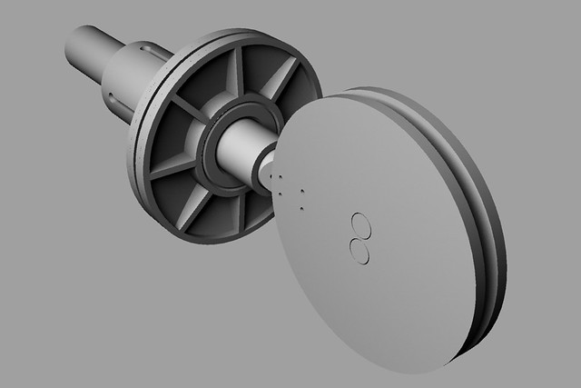
One difference between my DIY parabolic mic project and many others is that I made no attempt to fabricate my own dish. There’s an Ebay seller who makes 22″ Lexan dishes for under $50USD. Shipping to Hawaii was expensive, but the dish itself was pretty affordable. This was where the whole project started.

The Handle

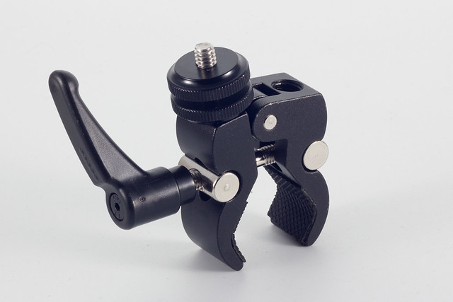
I like how the Telinga handles attach to their mics. The Avesrares article mentioned using auxiliary drill handles in a similar fashion, so I searched Ebay and found one of a suitable size for under $10US. The next step was to model a corresponding threaded tube and two screw plates to attach the handle to the dish.

DIY Parabolic - Clamp Tube and Collars Render

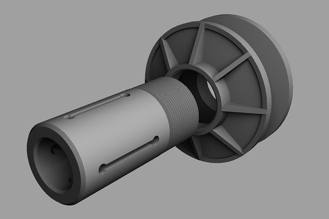
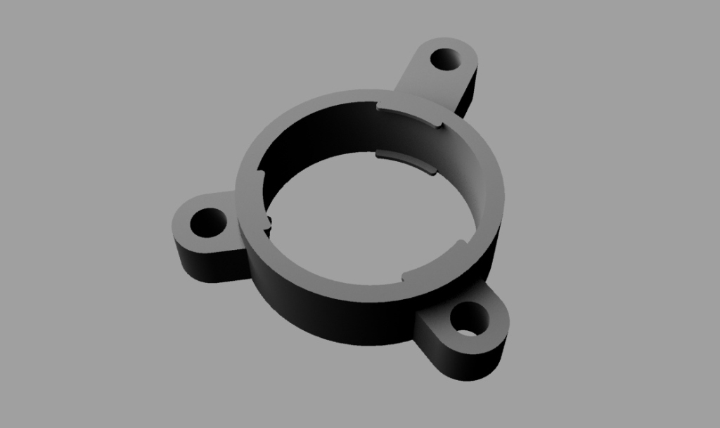
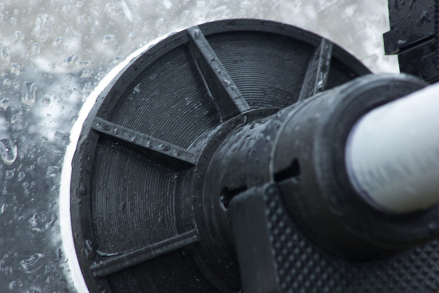
I wanted to be able to build interchangeable microphones, so I sized the inside diameter to take 3/4″ schedule 40 PVC pipe. The screw plates are 4″ in diameter – about the maximum my 3D printer can handle. The screw pitch is 14 TPI (sorry, metric system), and was sized to fit the outside diameter of the tube. If I remember right the threads left 10% flats top and bottom, and I left 0.020″ clearance between the tube and the screw plates. (They meshed great, too. W00t!)

Since these are sandwiching a parabolic form, the inner surfaces of the screw plates are curved to match. I added a layer of craft foam inside and out in an effort to provide some damping for handling noise (which it didn’t) and to make a nice snug fit (which it did.) Everything went together fine.
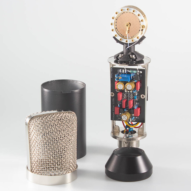
DIY Parabolic - Clamp Tube and Collars

The Microphone

In an article written by Klas Strandberg from Telinga Microphones, he explains that the focus of an acoustic paraboloid isn’t a precise affair. The mathematical focus of the paraboloid will be the point of best focus, but the size of the region of focus is frequency-dependent. I’d try to paraphrase here, but the article puts it so well there’s really no point. If you’re interested, read his article.

The upshot is that you can, to some degree, adjust the EQ of a parabolic mic by shifting where the capsules are with respect to the point of best focus. I knew I wanted some latitude, but I didn’t know how much range I might need. So I cut the 3/4″ PVC pipe a little long, reasoning I could always cut it down later.

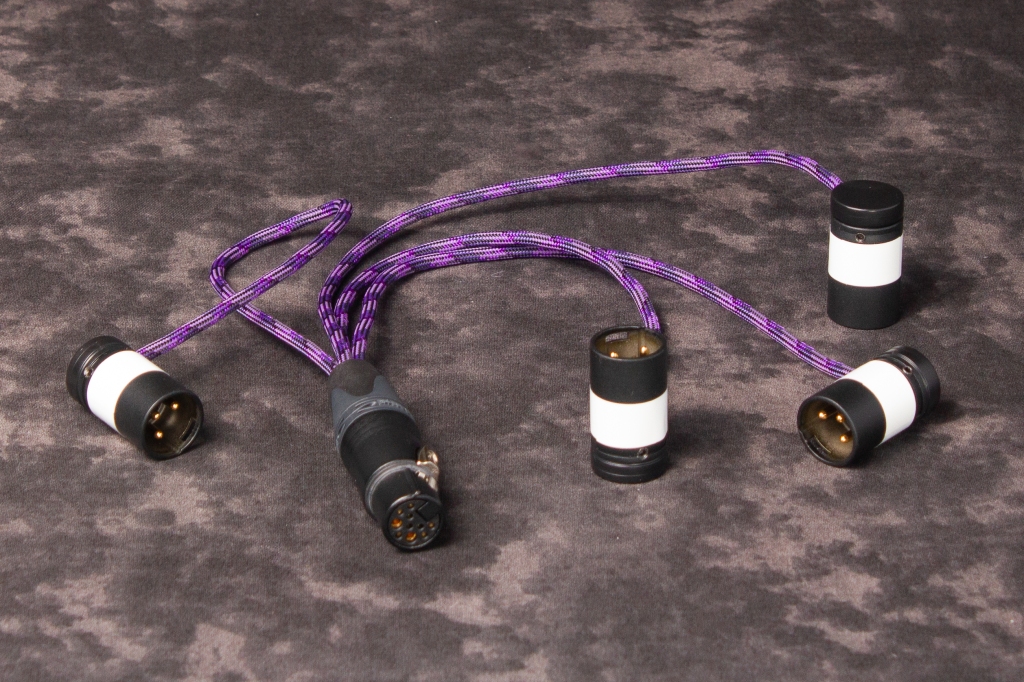
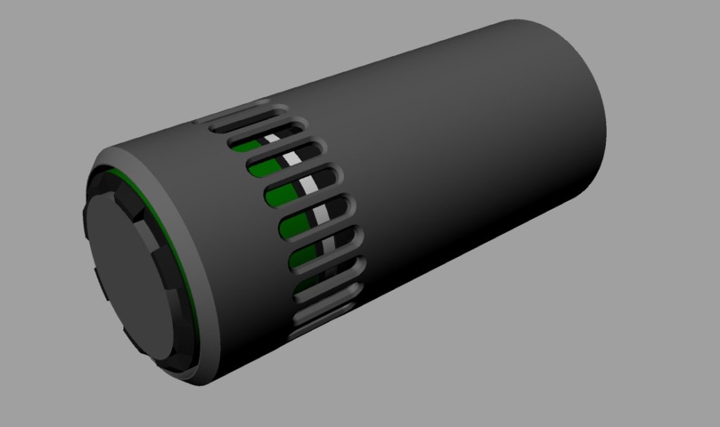
One bonus to using 3/4″ PVC pipe is that Neutrik XLR connectors are a nice snug press fit into the tube. Since I was planning to make a stereo microphone, and since I’d already built an XLR-5 to twin XLR-3 splitter cable for my MS Alice microphone, I used an XLR-5 connector for this mic as well. While not the most elegant setup for this connector, it was an expedient solution that let me get on with the business of building the rest of the microphone. I can always revisit this later.

(As a quick aside, “I can revisit this later” is designer code for “You’re going to see this in the final version.”)

DIY Parabolic - Handle, XLR5 Connector, and Reflex Sight

My first design for the business end of the microphone followed the logic in the Avesrares article: a baffle that splits the dish left-from-right and a second baffle facing the dish. Unfortunately my dish has a shorter focal length than its depth, so adding the second baffle would’ve cut off about half the surface area of the dish.

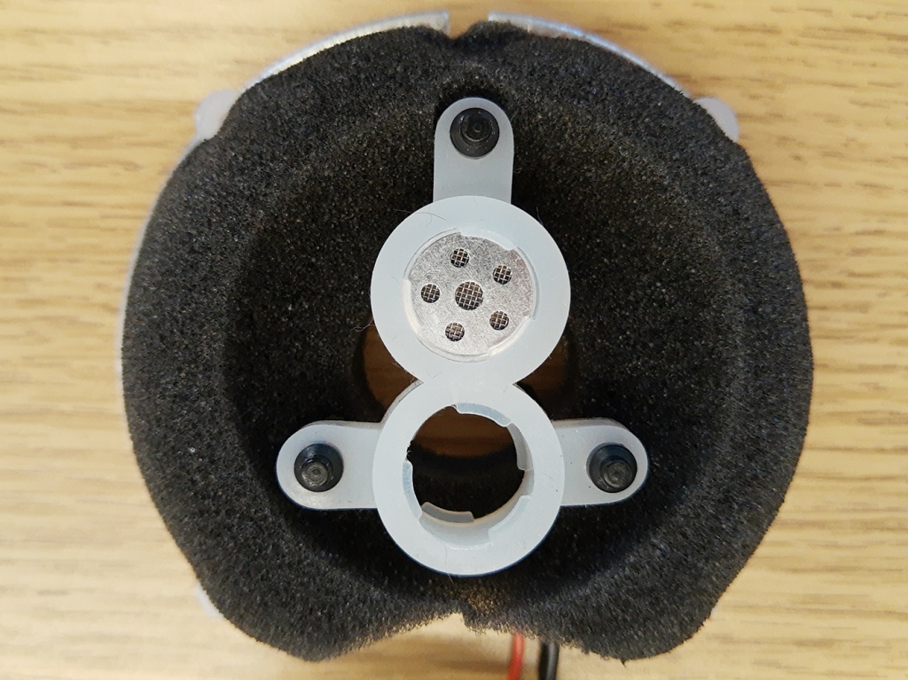
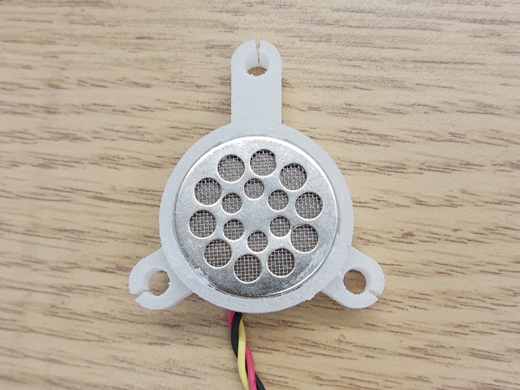
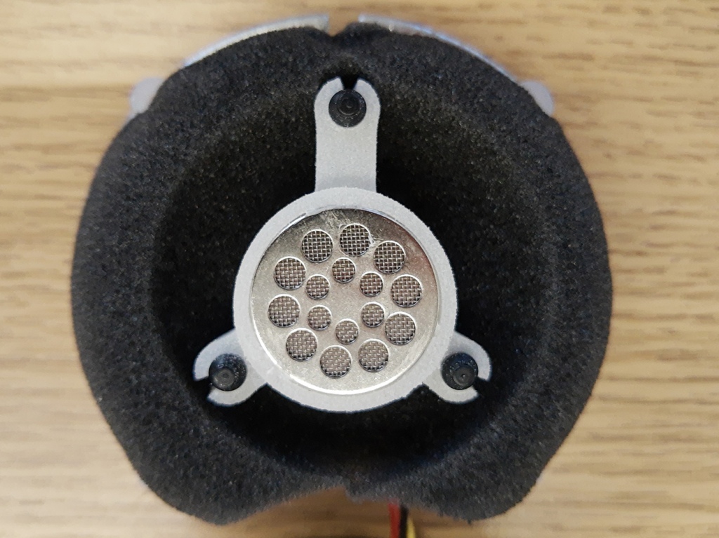
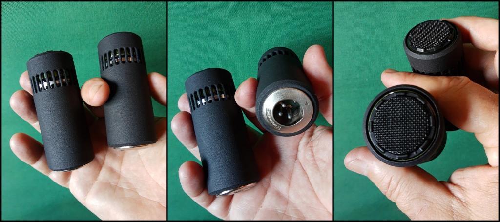
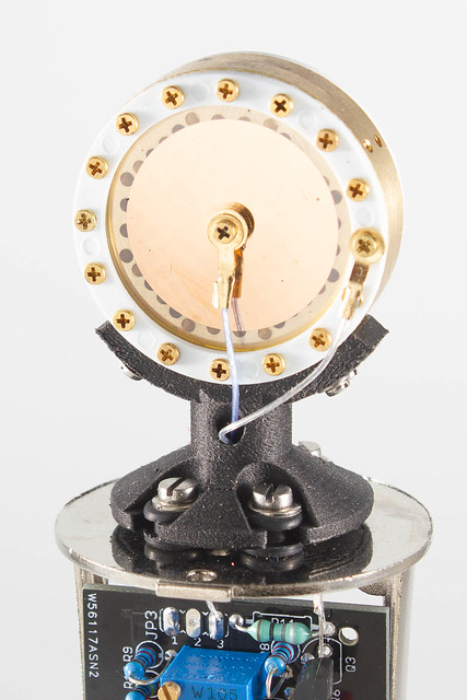
Instead I went with a baffle similar to the one used on the Telinga microphones, except that instead of using the microphone capsules as pressure zone transducers (PZT), I stuck to familiar territory and arranged them as boundary mics. I’m not 100% sure this was an ideal approach since it moves the diaphragms of the capsules away from the axis of the dish, limiting how close they can get to the point of best focus in the radial direction. Still, it worked.

DIY Parabolic - The Giant Lollipop - Render

Originally I’d intended to make solid baffle plates on the 3D printer, but these would’ve been costly in terms of material and time. Instead I took a tip from the SASS I built and made them only 1mm thick. This made for a very thin, unfortunately flexible plate with a high resonant frequency. I backed it with Dynamat, which does an excellent job of damping vibrations, and sandwiched dense latex foam between the two plates to provide further damping. The whole stack wound up being acoustically dead to handling noise. (But more on the handling noise later.)

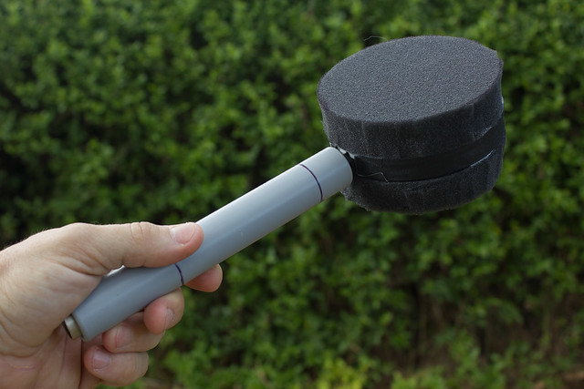
Unfortunately, before I took any pictures of the finished parts I stuck open celled foam on either plate to provide wind protection. So the only photos I have look like a big foam lollipop.

DIY Parabolic - The Giant Lollipop

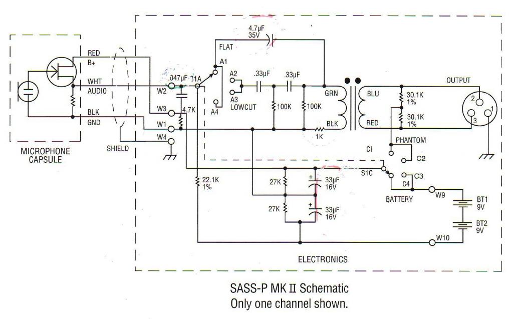
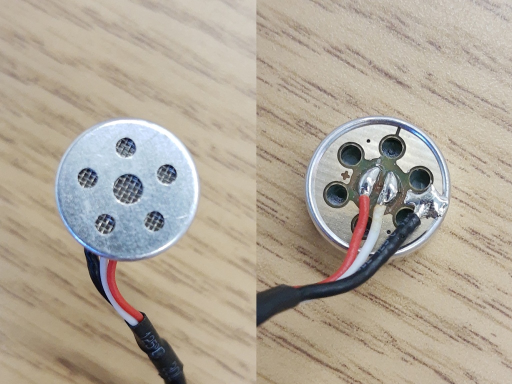
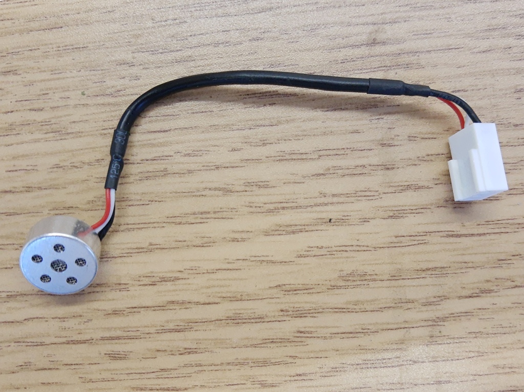
I wired the capsules using the same pattern as Vicki Powys’s SASS, except instead of wiring them into a 3.5mm TRS plug, I wired them into the XLR-5 connector using David McGriffy’s and Ricardo Lee’s Simple P48 circuit. Tuning the resistor for the Simple P48 circuit took some experimentation since each circuit was now driving two capsules instead of one. I’d quote the value of the resistors I wound up using, but there’s really no point. If you choose to build one of these, best to tune the resistors to get the bias voltage you want for your capsules.

With everything closed up, the microphone slides into the clamp tube on the dish and locks into place by twisting the drill handle. Voila, the DIY stereo parabolic microphone.

DIY Parabolic - Finished and In the Field

The Bling:

With such a narrow pattern microphone, I erroneously thought I’d need some way to aim it. (I’ve since used it in the field enough to know you aim these things by ear and not by eye.) One of the remnants of a previous project of mine, the camera helmet, was the small reflex sight I’d used for aiming the cameras. I mounted a short length of Weaver rail to the drill handle using a 3D printed adapter, and clamped the reflex sight to the rail. Voila, a neat looking, but ultimately useless addition to the parabolic mic.

This was rendered even more useless by the next bit of bling.

DIY Parabolic - Useless Reflex Sight
Wind Protection:

After some initial testing in the field, I found I wanted the option of another layer of wind protection. The foam on the lollipop was nice, but it wasn’t really enough to stop the kind of wind you get outdoors. (Foam is never enough to stop real wind. Like ever. Eventually I will learn.)

DIY Parabolic - Wind Protection

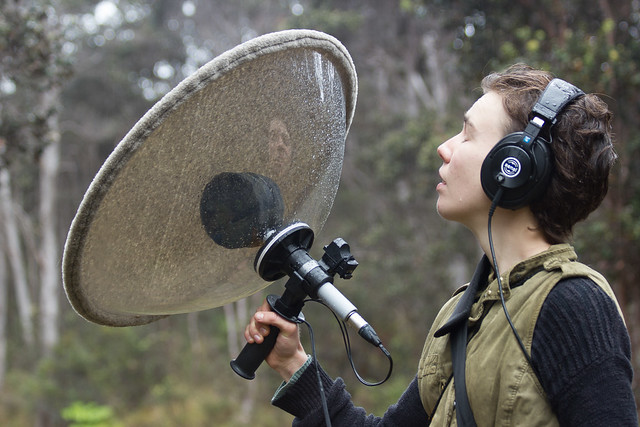
Chris Owens wrote a really good article describing the wind protection he made for his Telinga parabolic mic. I followed his directions to the letter and wound up with a very serviceable (and machine-washable!) cover for my mic.

DIY Parabolic - Wind Protection Detail

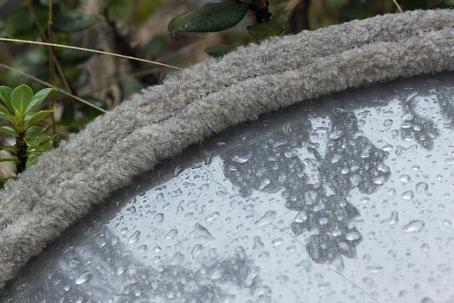
He used his dish to measure a circle of cloth, and rolled a hem at the edge that holds a length of shock cord. Once the hem is finished, the shock cord is pulled tight(ish) and is tied off. Chris Owens cautioned not to pull the shock cord too tight or the dish will warp. I made mine just snug enough to make sure the cloth stays on unless I’m ready to pull it off.


Post Script:

Now that I’ve had the chance to use my dish in the field I’ve found a number of shortcomings I’m planning to address in the future:

  • Anything you can’t put a shoulder strap on is lame – My dish is incredibly awkward to carry on a trail. Klas at Telinga solved this by making 1mm thick dishes that can be rolled up and carried in a shoulder bag. I’m sticking with my dish, but I have to add a shoulder strap. This is irritating.
  • Handles that can twist bother me – The drill handle I chose tightens (and loosens!) by twisting the handle. I’ve had it try to come undone in the field a couple of times when turning the dish. I’m planning to replace mine with a Bosch handle that uses a thumbscrew.
  • Handling noise is lame – I’ve been chasing handling noise on the BM-*00 conversion mics I’ve been building with some success, but this thing has it twice as bad. You can’t just shock-isolate the capsules. You have to shock-isolate the dish as well because it basically acts like a great big sounding board. Anything that’ll conduct handling noise to the dish shows up in the recording. A cushioned handle like the ones on the Telinga dishes would be a step in the right direction. For now I’m wearing gloves any time I use it.
  • I’m not 100% happy with the mic setup – The first prototype mock-up I did with this dish involved mounting my Alice M-S at the focal point of the dish. This worked way better than I suspected, and provided a better stereo image and a better mono image than the mic I’ve got in there right now. I’m thinking of recovering my four EM-172 capsules so I can go ahead and build that SASS surround mic, and building a dedicated mid-side mic to live in the dish.


And now for the rest…

First, A Sob Story:

I like to include audio samples in my build articles. Unfortunately I can’t for this one. Not yet, anyway. A little over a week ago I got some kind of outer ear infection in both ears. The tinnitus I’ve experienced for the last twelve years or so is about a bazillion times worse at the moment, and my right ear has lost about half its frequency range. I tried to edit a recording I’d made of a katydid and realized I couldn’t even hear the katydid in that ear. (And it’s not like they’re subtle or anything.) Even worse, my two ears currently hear broad-spectrum noise as two completely different sounds. Until this infection clears up, my ears are screwed. I can record, but I can’t edit. Sorry.

Second, A Note on the Photos and a Thank You:

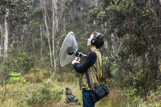
No, that’s not me holding the mic in the field. I was the one tripping the shutter. (I know which end of the camera I like to stay on.)

About half the pictures in this set involve wet gear. This is one of the hazards of recording in Hawaii: it rains. Rain is not ideal for recording with a parabolic mic. Each rain drop on the dish was picked up by the mic, and there were plenty of rain drops. I did make some recordings during the photo session, but because of the rain none of them really showed off the mic very well. Everything survived fine, though.

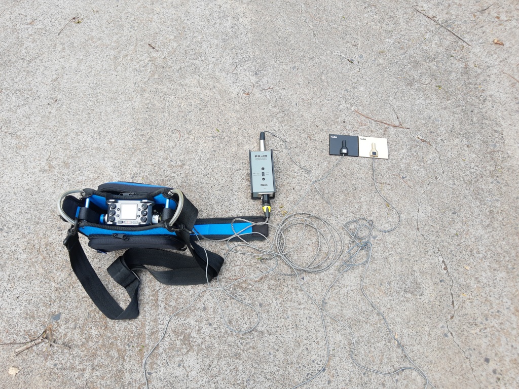
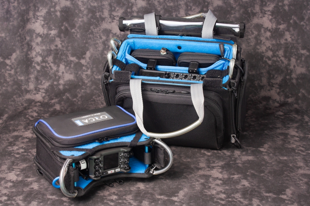
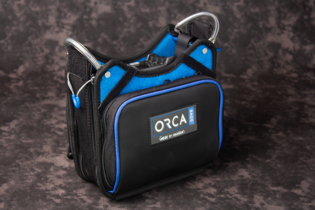
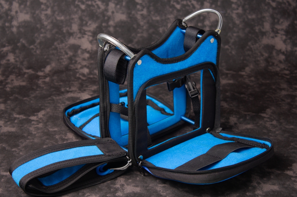
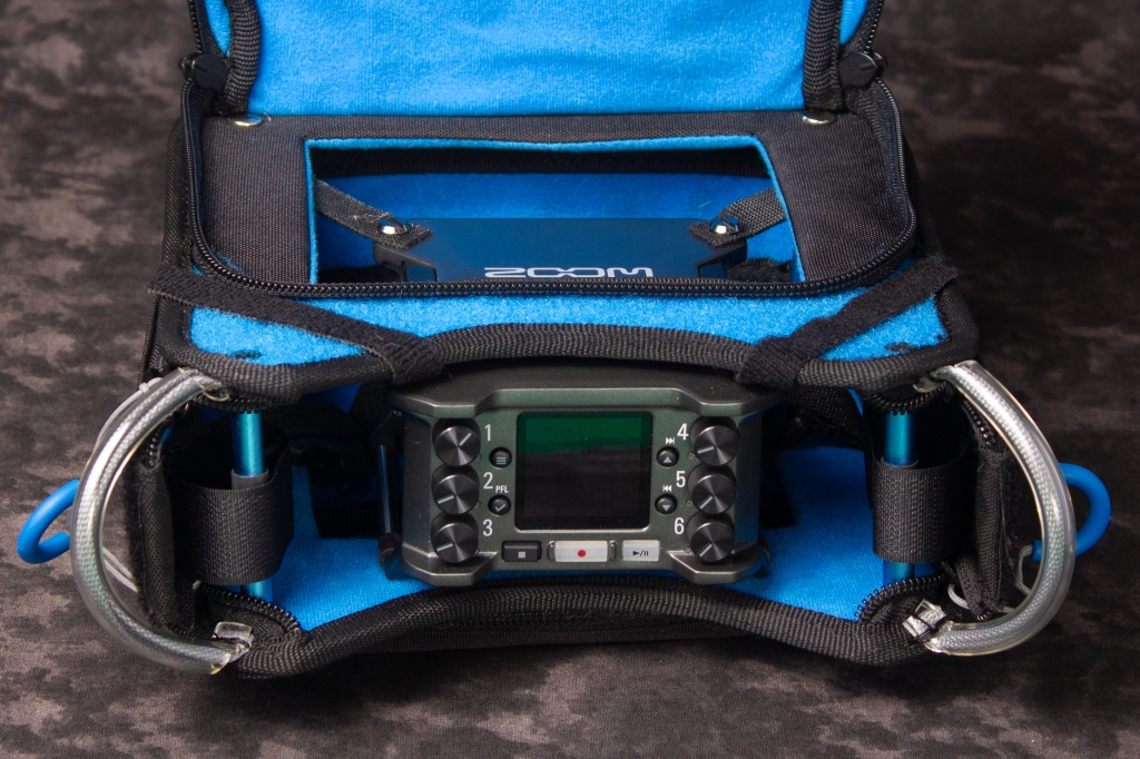
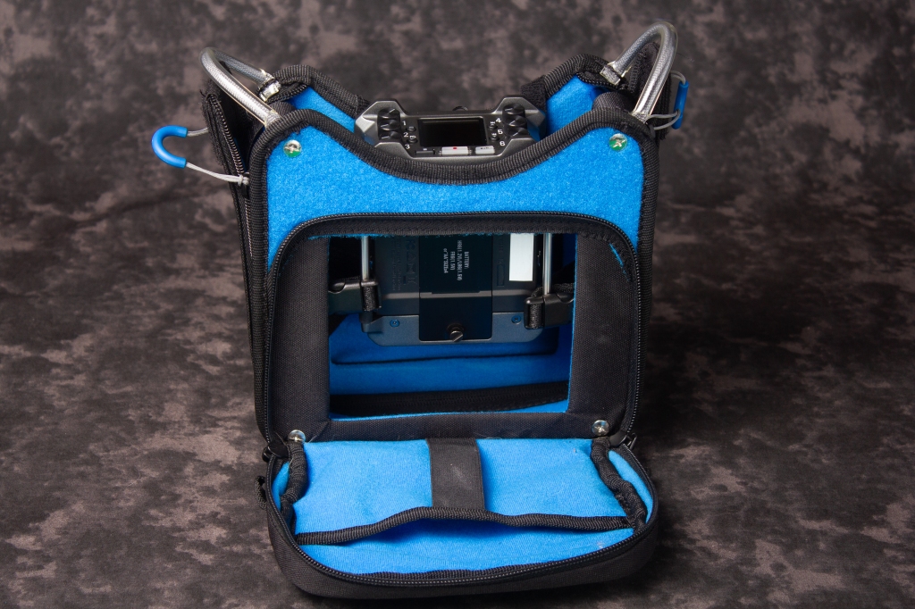
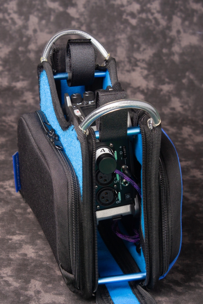
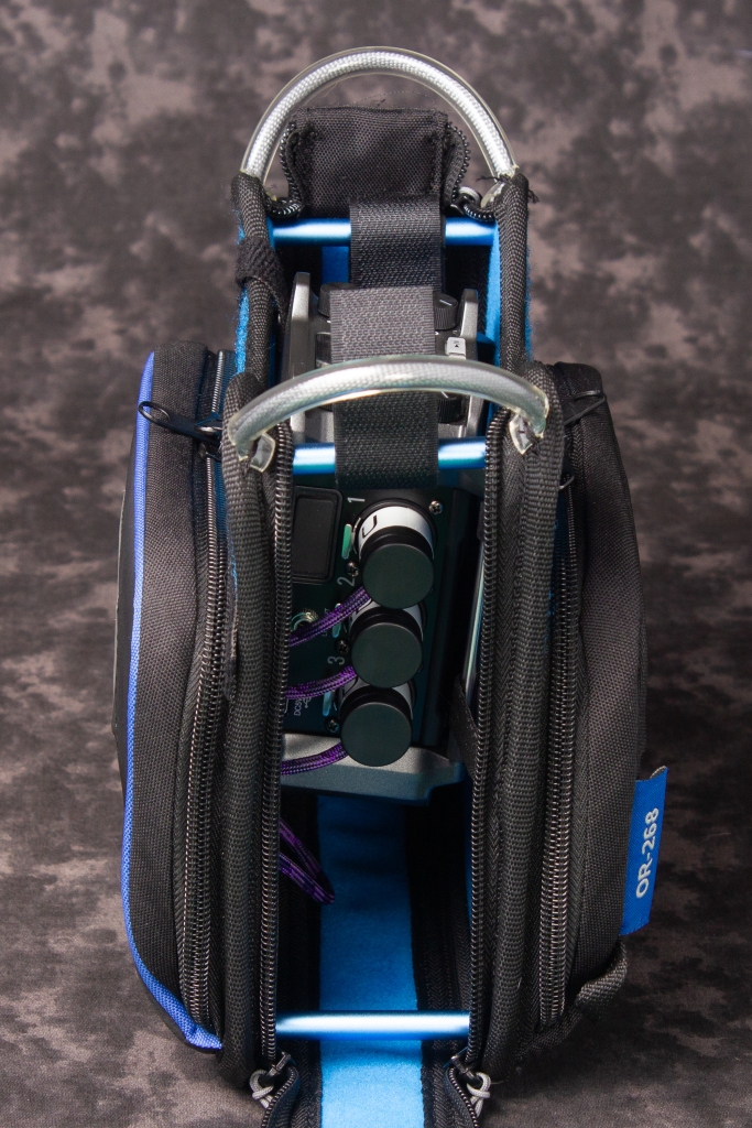
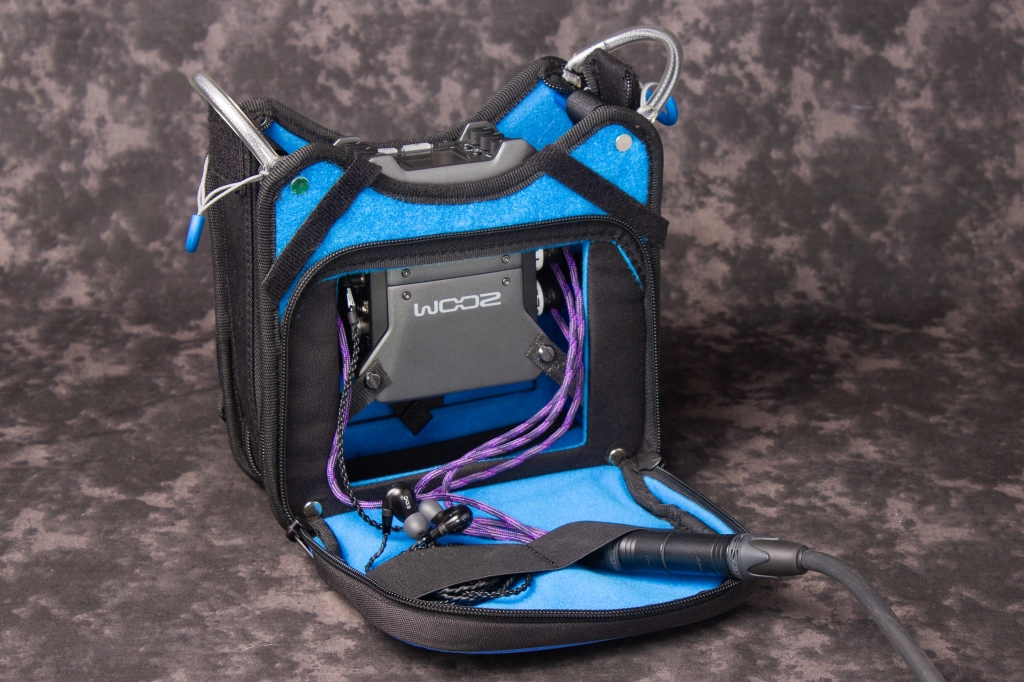
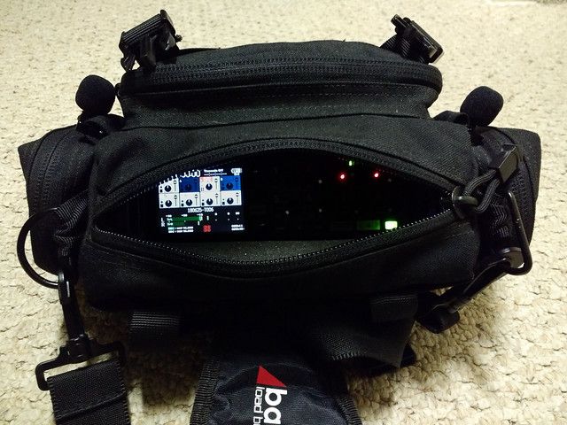
The black audio bag worn by the recordist in the photos is the brainchild of Andrew Jones, described in an article he wrote on WAV.REPORT, Tutorial: “DIY” Audio Drop Bag. Mine’s only about half finished (it still zips shut) but it’s a really good article and an unbeatable bag for the price. Thanks, Andrew!

Edit:

At the request of Benoît, I’ve made the STL files for my parabolic mic build available on Thingiverse. I’ll add them to Shapeways in the not too distant future as well, but for now they’re at least available:

Thingiverse

Cheers!

Posted in Uncategorized | 13 Comments »

Useful Little Clampy Things

Posted by Tom Benedict on 20/12/2017

A while back I needed the ability to put a 1/4″-20 threaded stud… Somewhere. Anywhere. Everywhere. I tried some things on the 3D printer, but realized none of them would be as robust as I needed these to be. So…

I turned to Ebay!

A Useful Clamp

Turns out you can get insanely cheap clamps by searching on “super clamp”. Some come with T-bar handles, some with offset handles like this one. Some come with articulated arms (which I used for mounting cameras on our vacuum chamber for work). And some just come with 1/4″-20 and 3/8″-16 threaded holes. Mine came with threaded holes.

I added the 1/4″-20 threaded stud by chopping the heads off some bolts and cleaning them up with a grinder and a die. The thumb screws came off of a camera hotshoe to 1/4″-20 adapter (also courtesy of Ebay.)

All in all these things came together for less than $6 apiece.

A Useful Clamp with Shock Mount

My original purpose for these was to be able to space mics anywhere I wanted across a bar for trying different stereo recording techniques. To do that I needed to be able to mount any of my self-contained stereo setups, all of which take a 1/4″-20 thread, or to mount individual shock mounts like this one.

A Useful Clamp with Ballhead

But there’s no reason to stop there. Pop a small ballhead on one of these and you can mount a camera, a handheld sound recorder, an off-camera strobe, or whatever else strikes your fancy.

The only problem I’ve found with these is that the handles like to come off, leaving the clamp firmly attached to whatever you cranked it onto. If you decide to get any of these, be sure to test them first, and if any handles come off, re-install them using red or green Loctite. (I had to re-install three of mine!)

I wound up building five of these, but now I wish I’d ordered more.

P.S. Since writing this, I’ve been told this is all pretty standard fare for lighting and grip gear on a film set, and that re-purposing lighting gear is a cheap and easy way to build solid recording setups. My take-away: 1 – There’s nothing new under the sun with this article. 2 – My butt’s gonna go numb the next time I sit down with the B&H catalog or start surfing their web site! 3 – Neither of these is a bad thing.

Posted in Uncategorized | Leave a Comment »