


BM-800 Microphone Conversion Part 2
Posted by Tom Benedict on 22/10/2016
This is the second half of a two-part article describing my conversion of a BM-800 microphone to an Alice microphone using a Transsound TSB-2555B cardioid capsule. All of this is based off of a pair of Instructables written by Jules Ryckebusch: Modify a cheap LDC Condenser microphone and Build the MS Alice Stereo Microphone.
Part 1 of this article showed pretty pictures of the donor mic (a Neewer NW-800 with an excess of bling), a description of the cable that came with the mic (which I don’t intend to use), photos of the mic in various stages of disassembly, and a CAD drawing of the salient features inside the microphone to help others lay out circuit boards for their own conversions.
Since writing part 1, all of the bits and pieces I ordered to do the conversion arrived: enough electronics to build three Alice boards, and a TSB-2555B capsule to put in the first one.

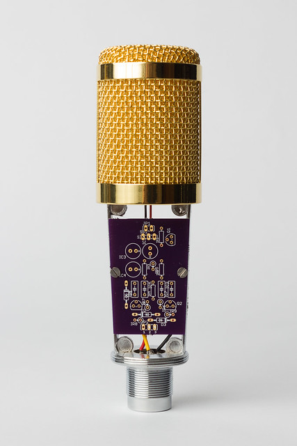
Before populating the boards I did a test fit to make sure they would actually fit. I was pleased to see how well the screw holes lined up, and I came pretty close with the taper.
The next step was to populate the boards. Opinions differ on how to wire the high-impedance (high-Z) end of the board, so I started with all of the low-Z components.
The circuit used in Jules’s first article had zener diodes on the output stage to protect it against over-voltage on the XLR pins. The circuit as-built in his second article omits the zeners since the 2N5087 transistors are rated for more than the 48V likely to be seen on an XLR connector. I ordered the zeners, but left them out for now.

After I’d already wired all the boards I installed one in the mic and ran into my first problem: With the board installed right-side-up, the 47uF capacitor pokes up high enough that it interferes with the body tube. For my first mic I’m planning to install the board up-side-down to give the capacitor more room. But if I wind up building the MS mic from Jules’s second Instructable, I’ll need to install new capacitors that lay flat against the circuit board.

The reason for the difference of opinions on the high-Z end of the circuit is that it’s sensitive to contamination: leftover solder flux, dirt, dirt combined with humidity, oxidization, etc. on the high-Z end can all cause unwanted noise in the mic. Jules soldered his components to the board without issue. Others have used Teflon standoffs to float that part of the circuit above the PCB. Homero Leal built his Charis mic by point-to-point soldering the high-Z components, letting them float above the board without standoffs. Scott Helmke, the original designer of the Alice circuit, solders the high-Z components directly to the back of the mic capsule. For my first pass at this I soldered the low-Z legs of the FET to the board, but floated the high-Z circuit without stand-offs, similar to Homero’s Charis mic. I can always change my mind later and re-wire them.

With the board built, the next step was to add 22nF capacitors between pins 1 and 3 and pins 1 and 2 on the XLR connector to provide additional RF noise filtering. After that I installed the modified connector and the board in the mic body.

The rest of the action takes place inside the headbasket.
It’s possible to cut away the original mic capsule to leave a saddle for mounting the TSB-2555B, but I wanted to make an entirely new saddle. Chalk some of this up to not wanting to make a modification I can’t back out. Chalk some of it up to my wanting a machining project to go along with the electronics project. Either way it needlessly complicates an otherwise pretty simple project.
Space inside the headbasket is tight, so rather than run into more interference issues I fleshed out the 2D CAD drawing and turned it into a 3D model. The space constraints almost entirely dictated the shape of the new saddle and post. The mic frame is drilled and tapped for M2.5 screws on a 10mmx15mm rectangular pattern, only two of which are used on the original saddle. I chose to use all four. The mic wires pass through holes spaced 20mm apart, centered on the long axis of the bolt pattern. In the CAD model I indicated these with 3.13mm holes, but in the final part I cut them as slots to make installing and removing the capsule easier.

I attached the TSB-2555B capsule to the saddle with E-6000 silicone adhesive. A better method for the saddle shape I used would’ve been a polyurethane adhesive like Gorilla Glue, but I wanted to be able to remove the capsule in case I decide to add shock isolation inside the mic to cut down on handling noise. As-built the capsule can be removed by passing a fine wire between the capsule and the saddle, cutting the silicone bond.
EDIT: The first time through, I missed an important step: One of the charms of the Pimped Alice circuit is the potentiometer next to the 1Gohm resistor. It allows you to bias the FET properly, regardless of which FET you use. The catch is that by definition, if you don’t do anything with the potentiometer it will not be properly biased! In all ignorance I soldered everything up, closed up the mic, and went testing. Even with an improperly biased FET it still performed beautifully. I did go back and do a proper job of it, though.
In Jules’s first Instructable, toward the end, there’s a nice write-up for how to bias the FET. The catch is that this step must be done before the capsule is soldered to the board.
With the FET properly biased and the capsule attached to the saddle and post, all that was left was to put it all together and close it up.

I did a quick side-by-side against one of my Primo-EM184 cardioid mics. The Alice runs a little hotter, but not by too much. I’m reserving further judgement on the new mic until I have a chance to get it out in the field and try it on some quiet sources.
Tom

Building the MS Alice Microphone – Part 1 « The View Up Here said
[…] was already covered in another pair of articles: BM-800 Microphone Conversion Part 1 and Part 2. The major differences between that microphone and this one are a change in capsules (Transsound […]
Building the MS Alice Microphone – Part 2 « The View Up Here said
[…] Modify a Cheap LDC Condenser Microphone, namely: BM-800 Microphone Conversion Part 1 and Part 2.) I also covered my design for the saddle and post that holds the three capsules in the particular […]
steph sandberg said
Hi Tom,
Here I go, I dive into to the real stuff, I am building the Alice! I am not even trying to understand the circuit this time, that’s way over my league, even though I ended up understanding SimpleP48 thanks to you (see https://tombenedict.wordpress.com/2016/03/05/diy-microphone-em172-capsule-and-xlr-plug/#comment-3250). So I am trying to figure out the basics: what to buy… I already got a BM700 that would not permanently destroy my retinas. (ahem…) Fun fact: I have a much larger capsule size than you did in the BM 800, about the size of the T165s but the body seems identical. Same size. So the grill seems interchangeable which is cool. I also got the capsules–really quickly considering I am in Europe, thanks JLI.
I will let you know how it goes, I already asked for some help in the micbuilders group…
In the meantime I wanted to send you photos over email about heatsink soldering in response to your last reply, but couldn’t find anyway to contact you directly could you drop me an email so I can do so?
simon said
hi TomHello
first of all I congratulate you for the great job you did with this conversion.
would you have a list of components (especially the circuit print)
do you have a store to advise me to buy it
Thx
Simon
Tom Benedict said
The bill of materials for all of the components is in Jules’s original article. (If it’s not, let me know and I can get you a copy of the last one I used.) He should also have the Eagle files for the PCB he used in there as well. The only real change I made to the PCB I used for this build was to change the outline of the board to fit the taper in the BM-800 microphone internal frame. I can make that one available to you, if you like.
denis said
Hi, is it possible to connect RK-87 mic capsule to this board modification?
Tom Benedict said
Unfortunately, no. Not with the board I used for this mic.
However, Homero Leal, the original designer of this board, has another board he’s selling on Ebay that works quite well with the RK-87 capsule. My latest mic build uses a slightly earlier version of this one in conjunction with an RK-87 capsule:
https://www.ebay.com/itm/HL-Pimped-Alice-V-40-Microphone-PCB/253602172257?_trkparms=aid%3D111001%26algo%3DREC.SEED%26ao%3D1%26asc%3D20160908105057%26meid%3D62548e06aa9a48368ec5dd6bee85f7b9%26pid%3D100675%26rk%3D3%26rkt%3D15%26sd%3D292582863215%26itm%3D253602172257&_trksid=p2481888.c100675.m4236&_trkparms=pageci%3Af85a9bc5-682b-11e8-a41c-74dbd1802fcf%7Cparentrq%3Acc3becb31630ab13282927a8fffe5937%7Ciid%3A1
https://www.ebay.com/itm/HL-Pimped-Alice-V-40-Microphone-PCB-Gold-Plated/253602179538?_trkparms=aid%3D111001%26algo%3DREC.SEED%26ao%3D1%26asc%3D20160908105057%26meid%3D62548e06aa9a48368ec5dd6bee85f7b9%26pid%3D100675%26rk%3D4%26rkt%3D15%26sd%3D292582863215%26itm%3D253602179538&_trksid=p2481888.c100675.m4236&_trkparms=pageci%3Af85a9bc5-682b-11e8-a41c-74dbd1802fcf%7Cparentrq%3Acc3becb31630ab13282927a8fffe5937%7Ciid%3A1
The first one is the standard v.40 board. The second is the gold plated version of the v.40 board.
I’m a big fan of Homero’s v.39 and v.40 boards. They can both be set up to work with an electret capsule with an in-built FET (e.g. EM-172), an electret capsule without an internal FET (e.g. TSB-2555B), and with un-polarized capsules like the RK-87. As long as you use good components, the results sound quite good.
Cheers!
Nigel said
Hello Tom Benedict,
Interesting project! I have bought four BM-800 from aliexpress and am wondering is it possible to use the stock capsule that is embedded in the BM-800s?
Regards,
Nigel
Tom Benedict said
It’s possible to re-use as much as you want.
The BM-800 mics are a little odd in that, depending on which one you get, you can wind up with any number of different configurations. The first two I got had very small electret capsules that had a less than stellar frequency response. Same with the next three. But the most recent two (from the same vendor as the previous set!) came with TSB-165A capsules, which sound quite nice. (They’re the basis of Jules Ryckebush’s Mid-Side Alice.) I wound up swapping out the capsules on those mics, anyway, since they were my first 34mm LDC mics, but I held onto the TSB-165A capsules for future projects.
Aside from the frequency response, the only other reason why you might not want to use the stock capsule is if it has an in-built FET, like the first BM-800 mics I bought. It’s not impossible to interface these to the Alice board, but it requires some careful choices when populating the board and wiring in the capsule. Henry Spragens has a good overview on his web site, Audio Improv, in which he goes into some of the differences in the basic circuit when using a capsule with the FET built in:
http://www.audioimprov.com/AudioImprov/Mics/Entries/2015/4/23_Basic_FET_Microphone_Circuits.html
This isn’t something I’ve done, though, so I can’t give you specifics other than what Henry’s got on his site.
Cheers!
Tom